





Choosing the right Cross Rollers begins with the application, not the catalogue.
Crossed roller bearings support radial, axial, and moment loads through perpendicular cylindrical rollers. Their compact structure suits semiconductor equipment, robotic joints, optical stages, medical scanners, and precision inspection machines. Grand View Research’s 2024 linear bearings analysis identifies automation and semiconductor manufacturing as major demand drivers. MarketsandMarkets also reports continued growth in precision motion systems, particularly where repeatability and compact designs matter.
Professor Alexander H. Slocum, a respected precision-engineering researcher at MIT, offers a useful principle: “Precision is not achieved by one component alone; it is created by the entire mechanical system.” That lesson applies directly to Cross Rollers. Rail stiffness, preload, mounting flatness, lubrication, contamination control, and thermal expansion must work together.
Small errors become visible quickly.
A lightly preloaded bearing may reduce friction, yet it can permit vibration under reversing loads. Excessive preload can increase heat, shorten service life, and make installation unnecessarily difficult. The best selection therefore depends on load direction, stroke length, speed, accuracy, environmental conditions, and expected operating hours.
Manufacturer catalogues provide valuable ratings, but they are not complete design decisions. Real-world alignment can differ from laboratory assumptions. This is where many selection guides become too confident. Engineers should compare dynamic load ratings, moment capacity, allowable speed, preload classes, and mounting tolerances before choosing a Chinese supplier or model.
The following guide examines China’s leading Cross Rollers options and explains how to match bearing type, precision grade, and supplier capability with practical equipment needs.
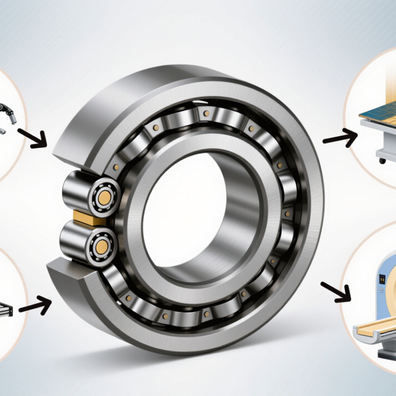
When choosing China-made crossed roller bearings, compare V, CRB, and CRBH designs by load, space, and mounting access. V designs commonly use V-shaped raceways, offering firm guidance and good moment-load resistance in compact mechanisms. They suit rotary tables, inspection stages, and robotic joints with moderate speed. However, “V” is not fully standardized across suppliers. Check the manufacturer’s sectional drawing, preload class, and accuracy table.
CRB is the conventional crossed roller bearing design. Its rollers alternate at 90 degrees, supporting radial, axial, and overturning loads through one bearing. CRBH is the slimmer version, with reduced radial section and lower weight. It saves installation space, but stiffness and load capacity may fall when dimensions are reduced. Do not select CRBH only because it looks efficient. Measure shaft deflection, mounting flatness, and expected moment load first.
A 2024 World Robotics report recorded 541,302 industrial robot installations worldwide in 2023, showing why compact, repeatable joint bearings matter in automated equipment. Industry selection data remains less uniform than robot data, which deserves caution.
For practical screening, use CRB for general precision axes, CRBH for restricted envelopes, and V designs where guidance and accessible assembly matter. Ask for runout, rotational torque, preload, hardness, and life calculations. ISO 281 remains useful for basic rating-life verification, but contamination and installation errors can dominate real service life. That part is often underestimated.
A clean 20-micrometre particle can still damage a precision raceway.
China Best Cross Rollers: How to Choose the Right Type?
Calculate Radial, Axial, and Moment Loads Using C₀ and M₀ Ratings
Choosing a crossed roller bearing starts with the real load path. C₀ indicates the basic static radial load rating. M₀ indicates the basic static moment rating. These values help prevent permanent raceway deformation. They do not directly predict service life. Measure radial and axial forces at the bearing center. Then calculate the moment with M = F × L. For example, a 500 N load placed 0.2 meters away creates a 100 N·m moment. Keep every unit consistent.
For combined radial and axial loads, use the supplier’s equivalent static load equation. Do not simply add the forces. Compare the calculated equivalent load with C₀. Compare the applied overturning moment with M₀. Apply a suitable safety factor for shock, vibration, emergency stops, and uneven mounting. A bearing may pass a simple calculation yet feel loose in operation. That is where the selection needs another review.
Tips: Sketch the mechanism before choosing a size. Mark each force and its distance from the bearing center. Check preload, mounting flatness, and bolt stiffness. Use the catalog’s load-combination chart when radial, axial, and moment loads act together. My early calculations often missed cable tension. Small overlooked forces can change the result.
China Best Cross Rollers: How to Choose the Right Type?
For cross roller bearings, ISO 281 offers a practical starting point. The formula is L₁₀ = (C/P)ᵖ × 10⁶ revolutions. C means basic dynamic load rating. P is the equivalent dynamic load. For roller bearings, p commonly equals 10/3. L₁₀ predicts the life reached by 90% of identical bearings under controlled conditions.
Check the numbers carefully. A 10 kN bearing carrying 2 kN gives about 213 million revolutions when p equals 10/3. That figure looks impressive. It is not a promise. ISO 281:2007 does not fully capture contamination, poor lubrication, misalignment, vibration, or mounting stress. In practical selection work, a small preload error can raise P and sharply reduce calculated life. I have seen clean laboratory calculations fail beside dusty production equipment.
Use the bearing supplier’s certified C value, not a copied catalog estimate. Measure real radial, axial, and moment loads during acceleration and stopping. The U.S. Department of Energy’s Operations & Maintenance Best Practices guide reports that predictive maintenance can reduce downtime by roughly 30–40% compared with reactive practices. For cross rollers, vibration checks and lubricant inspection can support that target. Recalculate L₁₀ after changing speed, preload, or load direction. The calculation is useful, but never complete.
| Crossed Roller Type | Typical Construction | Best Application | Load and Stiffness Behavior | Accuracy Considerations | Preload and Friction | Selection Check |
|---|---|---|---|---|---|---|
| Crossed Roller Ring Bearing | Two raceways and cylindrical rollers arranged alternately at 90°. | Rotary tables, indexing mechanisms, robotic joints, inspection equipment, and compact rotary axes. | Supports radial, axial, and moment loads simultaneously in a compact envelope. High overturning-moment stiffness is available when the bearing diameter is large relative to the applied moment. | Suitable when low runout, repeatable rotation, and a rigid mounting structure are required. | Preload improves rigidity and reduces clearance, but excessive preload increases friction, heat, and required drive torque. | Check radial load, axial load, overturning moment, mounting flatness, bolt pattern, and calculated L₁₀ life. |
| Crossed Roller Way | Roller cage and raceway pair used for linear motion. | Linear stages, measuring systems, optical equipment, semiconductor machinery, and precision slides. | Provides high linear stiffness and load capacity in a relatively small cross-section. Load distribution depends strongly on rail parallelism and mounting accuracy. | Best for short or medium travel where smooth motion and high repeatability are more important than long travel speed. | Light preload can improve motion quality. Excessive preload may cause stick-slip, higher drive force, and accelerated wear. | Check travel length, stroke frequency, acceleration, load center height, rail parallelism, and contamination control. |
| Split or Separable Crossed Roller Assembly | Separate inner and outer race components assembled around a shaft, housing, or mounting structure. | Applications requiring simplified installation, removable shafts, or special housing geometries. | Can provide high rigidity, but the final performance depends on housing accuracy, clamping, and raceway alignment. | Useful where service access or installation flexibility is important; mounting tolerances must be controlled carefully. | Preload is normally set during assembly. Adjustment should be gradual and verified by torque, runout, and temperature checks. | Verify assembly method, raceway alignment, preload adjustment range, shaft and housing tolerances, and service conditions. |
| Compact Crossed Roller Bearing | Integrated bearing with a small radial section and closely spaced rollers. | Compact rotary actuators, small positioning stages, camera mechanisms, and laboratory instruments. | Provides a favorable stiffness-to-size ratio, but allowable load and moment capacity are lower than those of larger-section bearings. | Appropriate where space is limited and moderate loads must be combined with controlled rotational accuracy. | Requires careful lubrication because the smaller internal volume can be more sensitive to lubricant quantity and contamination. | Check envelope dimensions, static safety factor, operating speed, lubrication interval, and thermal conditions. |
| ISO 281 L₁₀ Life Verification Examples for Generic Roller Bearings | ||||||
| Example | Application Condition | C: Dynamic Load Rating | P: Equivalent Dynamic Load | p Value | L₁₀ Basic Rating Life | Approximate Life at Stated Speed |
| A | Moderate rotary load with stable lubrication | 50 kN | 5 kN | 10/3 | (50/5)^(10/3) × 10⁶ ≈ 2,154 million revolutions | ≈ 299,167 h at 120 r/min |
| B | High-load rotary axis with a balanced load distribution | 100 kN | 10 kN | 10/3 | (100/10)^(10/3) × 10⁶ ≈ 2,154 million revolutions | ≈ 149,583 h at 240 r/min |
| C | Compact bearing with a relatively high applied load | 30 kN | 6 kN | 10/3 | (30/6)^(10/3) × 10⁶ ≈ 214 million revolutions | ≈ 59,444 h at 60 r/min |
| D | Linear-stage equivalent load converted to bearing load | 80 kN | 20 kN | 10/3 | (80/20)^(10/3) × 10⁶ ≈ 102 million revolutions | ≈ 14,167 h at 120 r/min equivalent speed |
| Practical Selection Criteria | ||||||
| Criterion | What to Determine | Recommended Engineering Check | Effect on Bearing Selection | |||
| Combined Loading | Radial force, axial force, and overturning moment. | Convert the actual load condition into an equivalent dynamic load P using the selected bearing manufacturer's calculation method. | A bearing with a higher C value or larger effective moment arm may be required when combined loads are significant. | |||
| Static Safety | Shock loads, emergency stops, clamping forces, and standstill loads. | Compare the maximum static equivalent load with the static load rating C₀ and apply an appropriate safety factor. | Static capacity may govern selection even when calculated L₁₀ life is adequate. | |||
| Rigidity | Required deflection under operating load and moment. | Evaluate bearing stiffness, preload, mounting structure, and raceway deformation together. | Higher preload and larger bearing geometry generally improve rigidity but may increase friction and heat. | |||
| Speed and Motion | Rotational speed, stroke frequency, acceleration, and duty cycle. | Check permissible speed, lubrication method, cage behavior, and temperature rise. | High acceleration or frequent reversing may require a suitable cage design, lubricant, and preload level. | |||
| Mounting Accuracy | Housing roundness, flatness, parallelism, shaft fit, and bolt tightening sequence. | Follow the applicable precision bearing installation tolerances and measure runout after mounting. | Poor mounting accuracy can reduce load sharing, increase friction, and shorten practical life even when the ISO 281 calculation is acceptable. | |||
| Environment | Dust, moisture, vacuum, temperature, chemicals, and cleaning agents. | Select seals, lubricant, corrosion protection, and maintenance intervals for the actual environment. | Contamination and inadequate lubrication can make actual service life substantially lower than calculated basic rating life. | |||
Choosing cross rollers for micron-level motion requires more than reading a load rating. Accuracy, stiffness, and runout must match the machine’s actual movement profile. In practice, start with the required positioning tolerance, travel length, applied load, and duty cycle. A roller guide with excellent accuracy may still perform poorly under uneven loading. Ask for measured data.
High accuracy reduces deviation along the travel path. Stiffness limits deflection when the carriage accelerates or carries an offset load. Runout controls unwanted vertical or lateral movement during operation. These values should be reviewed together, not separately. A guide with low runout is not automatically the best choice. Preload also matters. Excessive preload can increase friction, heat, and drive requirements.
During evaluations, measure motion under the real mounting condition. Use a calibrated indicator or laser system, and record results at several travel positions. Temperature changes can alter clearances by a few microns.
I once focused mainly on nominal load capacity and overlooked mounting flatness. The guide passed initial checks, but its motion became inconsistent after installation. Rechecking the base surface revealed the problem. This mistake remains useful. Selection should include mounting tolerance, lubrication, preload, and measurement repeatability. Small details decide performance. A reliable supplier should explain test methods, accuracy grades, and allowable runout instead of providing one attractive number.
When choosing cross rollers from China, treat ISO 9001 as a process signal, not a guarantee of precision. Ask for the current certificate, issuing body, scope, and covered factory address. The scope should include machining, assembly, or bearing production. A certificate copied into an email is not enough. Verify its validity through the issuing body’s public registry when available. Documents can mislead.
Request the exact material grade for rings, rollers, cages, and fasteners. Check heat-treatment records, hardness ranges, and lot traceability. A material certificate should show the heat number, chemical composition, test method, and supplier identity. For demanding motion systems, confirm that the stated grade suits your load, speed, corrosion exposure, and temperature conditions. Do not accept “high quality steel” as a technical specification. It proves little.
Reliable suppliers provide batch-level dimensional reports, not only blank templates. Review roller diameter variation, raceway geometry, preload, runout, and surface finish against a controlled drawing. Request calibrated instrument IDs, calibration dates, sampling plans, and nonconformance records. Photos of gauges help, but raw measurements matter more. I would compare three recent lots, because one perfect report may hide unstable production. Easy to overlook. A supplier may meet ISO requirements while missing your application’s tolerance. That gap deserves a trial order, witnessed inspection, and documented corrective action.
Supplier evaluation framework based on ISO 9001, material grade verification, and inspection data
The recommended evaluation model gives the highest weight to material grade verification and product testing because cross rollers require accurate hardness, dimensional stability, and reliable load performance. ISO 9001 certification supports process consistency, while traceability and packaging help reduce quality and logistics risks. Use these weights as a supplier-comparison checklist rather than as company-specific performance claims.
No, I will think about it in future.


